I had forgotten how time-consuming this type of project is. Perhaps I’m just overly cautious, but I figure you’re always better of getting it right the first time than doing rework later. Usually, things I build work first time, so I think this approach does pay off. So here are a few suggestions for a project like this:
- Measure each resistor with a digital multimeter before putting it in place.
- Check each component and surrounding connections against the schematic before fastening it in place.
- Make sure that each component has a secure physical connection before soldering – don’t rely on solder to hold it together.
- Check the components against the schematic again before soldering.
- When soldering, apply heat to the terminal strip or socket terminal first, and when it “wets” then apply heat to the connecting leads. Remove the iron as soon as the assembly wets. (In other words, don’t overheat components.)
With this project, I decided to do the signal components first, before mounting the heavy components like the transformers. Usually, the transformers and chassis parts are mounted first and the wiring from them done before wiring up the sockets and surrounding components. Doing it the way I’ve done it means leaving some connection points incomplete, and keeping a mental (or actual) note about which places will need connections made later. So it’s not the simplest approach but I wanted to do it this way this time.
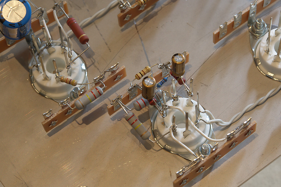
As noted above, it’s important that each component has a reasonably secure electrical and physical connection. Here are the signal components mounted but not soldered, not including the coupling capacitors. (I’ve left those off for now as they would obstruct soldering iron access to some of the points needing cable wiring.)
(Click on photos to enlarge.)
It’s important that some sensible layout constraints are observed. Anything that gets hot – such as the cathode resistors – needs to be positioned so that it gets airflow for cooling. Grid-stopper resistors should be located and soldered as close to the tube pin as possible. You will also note the use of twisted-pair wiring for the heaters, and keeping them away from signal wires (within reason):
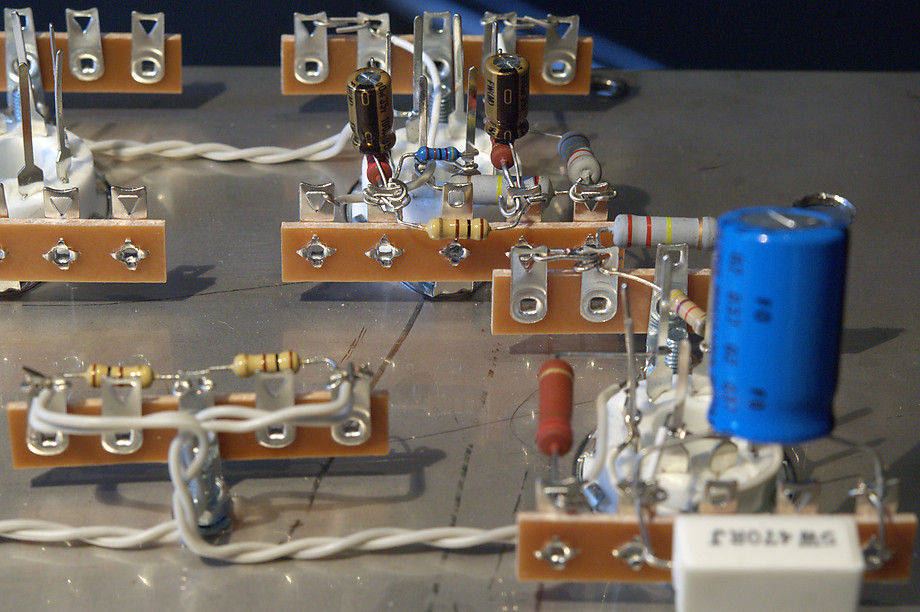
The tube sockets that Earle supplies are wire-wrap types. This is new to me but they worked very well – after soldering the components already attached to each pin, I simply cut off the pin above the soldered connection.
I then added the wiring for the terminal strip connections that needed it, and soldered them along with the components attached to the terminal strips. Finally, the coupling capacitors were soldered across the terminal strips as previously planned. Here is the result with one channel completed this way:
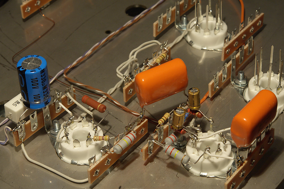
Next I need to do the other channel the same, and then wire up the input connectors and volume control. After that I will need to mount the heavy iron and build the power supply.